Antenna before winter: a check-up in one afternoon
Winter doesn’t ruin an antenna in a day. Water slowly creeps into a poorly sealed connector, sun and frost make tape brittle, and in March it turns out the repeater is “somehow weaker on receive”. I show what to check in autumn, while it’s dry and warm: measuring the coax (from the shack first), sealing the connector with two tapes, the cable run, mast and earthing. At the end there’s a checklist to tick off.
self‑amalgamating tape + PVCseal from +5 °Cwater in the cable can lower SWR12 inspection points
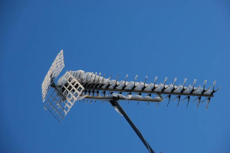
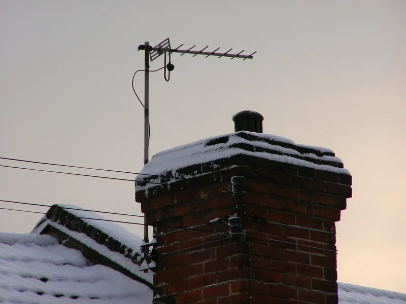
UHF antenna with rime ice · photo: Vestman, CC BY 2.0, Flickr
Before you go up on the roof
Choose the day, not just the tools
Half the battle is the weather. Tapes and sealing compounds have their temperature limits, and wet roofing felt and wind are a sure route to an accident while working on the antenna.
+5 °C
Warm
PVC tape Scotch Super 33+ can be applied even at −18 °C, but butyl tape needs above 0 °C, and Coax‑Seal compound needs +4.5 °C or more. Take +5 °C as the lower limit and keep the rolls in your pocket until the last moment.
0 mm
Dry
Not in rain, fog or after overnight frost. The manufacturers’ instructions agree: the cable and connector must be dry and clean, otherwise you’ll seal water under the tape for the whole winter.
10 m/s
No wind
10 m/s is the threshold from regulations on scaffolding and installation work, not a general ban — but a sensible limit for a radio amateur too. Diamond say plainly in the X200 manual: do not install the antenna on a rainy or windy day.
2 people
Not alone
In the X200 manual, Diamond advise against installing the antenna on a roof by yourself. Even on a flat roof someone should know you’re up there, and it’s best to tether your tools — a spanner falling from the roof of a block of flats is a real hazard.
!
Under health and safety regulations working at height starts at just 1 m above the floor, and at the edge of a flat roof fall protection is required. These rules apply to companies, not hobbyists — but the physics is the same. Wet roofing felt, leaves and morning frost are slippery; do not go onto an icy roof at all.
Diagnosis from the shack
Measurement first, then the ladder
You can catch the first symptoms without going on the roof: the SWR of the whole path and the analyser’s TDR/DTF mode. To test cable attenuation you need to temporarily disconnect the antenna at the top — and do it with an analyser or a NanoVNA, not with the radio.
Trap: good SWR, bad cable
A wet cable turns into a distributed dummy load. The wave reflected from the antenna returns through the cable and loses on the way just as much as the forward wave — so at the radio you see the reflection weakened by double the cable loss.
Example: the antenna has SWR 3, and after getting wet the cable attenuates by 6 dB. At the radio the meter will show SWR about 1.3, and with a dry cable it would show about 2.0. That’s why a suspiciously low SWR that “improved by itself” is just as much a red flag as a rising one.
Cable test with an open end
Disconnect the antenna from the cable at the top. Leave the cable end open — with nothing on it — and protect it from rain.
Connect an analyser or NanoVNA at the radio end (calibrate the NanoVNA SOL at the end of the lead you use to connect) and measure SWR or return loss at 145 and 435 MHz. Never transmit from the radio into an open cable — SWR 5–9 is a quick way to damage the power amplifier.
Cable loss is half the return loss measured at its input. From SWR alone you can read it from the table.
Compare with the datasheet. A result clearly worse than in the cable’s spec sheet suggests water — the analyser’s TDR/DTF mode will even show where.
i
Analysers have their limits: RigExpert AA-650 operates over 0…40 °C. In winter, measure with the cable brought indoors or on a warm day. Record the result — next year you’ll have something to compare against.
SWR with open end
Cable loss
8.7
1 dB
5.2
1.7 dB
4.4
2 dB
3.0
3 dB
2.3
4 dB
1.7
6 dB
20 m of cable (datasheet)
144 MHz
432 MHz
Ecoflex 10
0.9 dB
1.7 dB
Aircell 7
1.4 dB
2.6 dB
Attenuation from SSB datasheets (144 and 432 MHz). If 20 m of Ecoflex 10 with an open end shows at 70 cm SWR below 3, the cable loses at least 3 dB instead of 1.7 — time to look for water. For conversions: cable loss calculator and SWR calculator.
The weakest point
The connector: two tapes, in this order
Self‑amalgamating tape seals; PVC tape protects it from sun and abrasion. According to 3M’s datasheet, Super 33+ protects against moisture best when it’s the outer layer over rubber tape or sealing compound. Conclusion: PVC tape alone is not enough.
1
Dry and clean
The connector and cable must be dry. If, after cutting away the old tape, there’s water inside or green verdigris on the braid, cut the cable back to clean, bright copper and fit a new connector — and then do a loss test, because the water may have travelled further.
2
Tighten, but with care
An N connector is tightened by hand — manufacturers specify 1.7–2.8 N·m, which is less than you’d think. Silicone grease, if you use it, only a thin smear on the gasket and thread, never inside on the pin and socket.
3
Self‑amalgamating tape
Start about 2.5 cm before the connector, finish 2.5 cm past it. Stretch hard until the tape narrows to ½–¾ of its original width, each turn overlapping the previous by half. The layers then fuse into a single rubber sleeve with no gaps.
It should extend 2.5 cm beyond the rubber on both sides. On a vertical run, wrap from bottom to top — like roof tiles, so water runs over the overlaps, not under them. Lay the last turn without tension and cut it with scissors: a torn tape unwinds over time.
e.g. Scotch Super 33+ or 88 · black, UV‑resistant
5
Do not block the drains
If the antenna has a drain or vent hole at the bottom, leave it clear — that’s what CommScope say in their sealing guide. This is where any water that still gets inside drains out. When the connector sits in the support tube, as in the X‑200, seal the accessible part and make sure water isn’t running down the tube straight onto the connector.
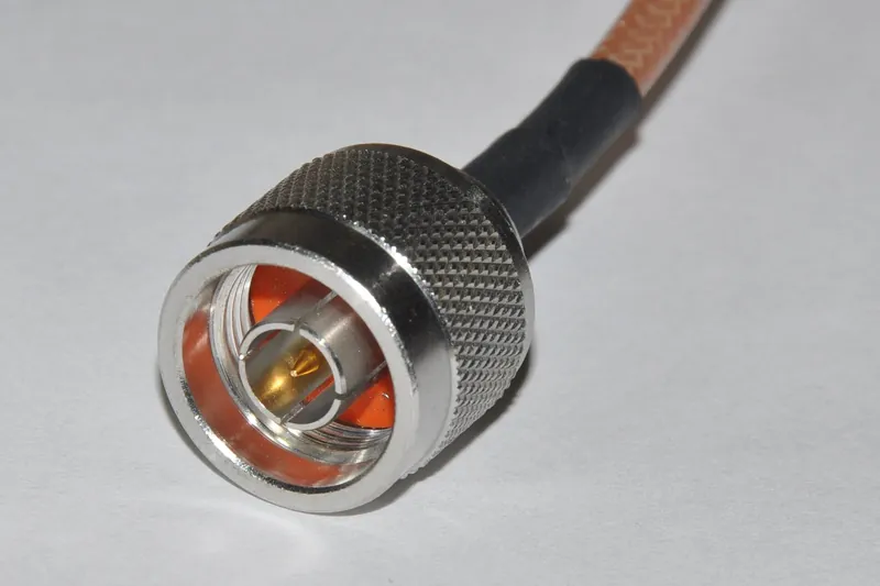
N plug: the seal protects the contact, but not the thread · photo: Joe Ravi, CC BY-SA 3.0, Commons
Connectors
N or PL‑259?
An N connector has a seal and is weather‑resistant; a UHF connector (PL‑259/SO‑239) is not. Even so, professionals tape over N as well: the seal protects the contact, but not the thread and not the point where the cable enters the connector. With an antenna with an N socket, like the Diamond X‑200N, don’t put N↔UHF adapters on the roof — each is another place for water.
Caution
What not to do
Do not seal with ‘acetic’ sanitary silicone: according to the Dow 732 datasheet it releases acetic acid while curing, which can corrode metal — especially in an enclosed space, and a taped‑up connector is one. Apply putty‑like sealing compound over a PVC tape underlayer, because its crumbs in a PL‑259 thread can cause an intermittent contact.
An enemy you can’t see
Water in the cable: where it comes from and where it ends up
Water that once gets under the jacket wicks along the braid like a wick. It oxidises the copper, increases losses in the dielectric, and when frozen can burst the cable.
Symptoms
SWR “wanders” after rain or slowly changes over months — upwards or, worse, downwards.
Weaker repeater signals and poorer reports at the same SWR — the cable is simply eating the signal in both directions.
Green or black braid after slitting the jacket by the connector. The copper should be bright.
How to run the cable
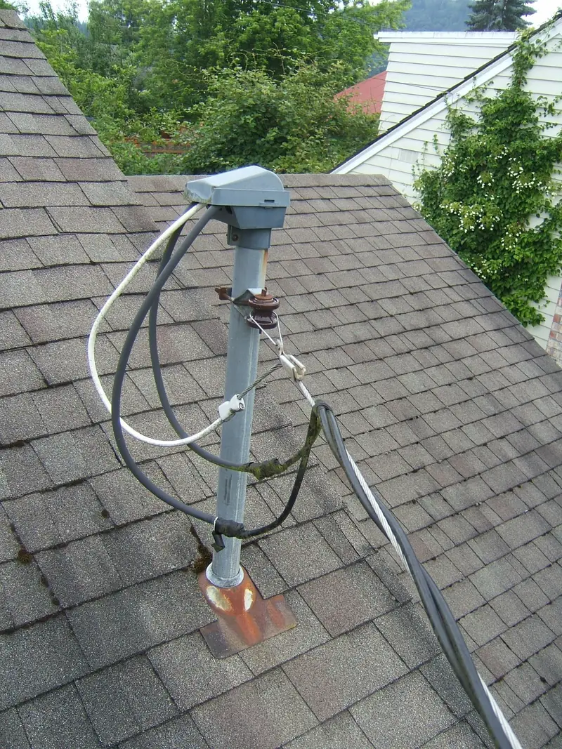
Always downwards from the antenna. Water runs along the jacket, so the cable must not carry it back to the connector. Before every place where the cable turns upwards or enters the building — the roof edge, gutter, pass‑through, window — make a drip loop: a gentle “U” from whose lowest point the drops fall.
The loop radius must not be smaller than the minimum bend radius from the cable datasheet — for Ecoflex 10 it’s about 4 cm for a one‑off bend and 8 cm if the cable is to move. Fix with black UV‑resistant ties and don’t tighten them so much that they crush the cable.
≈
A drip loop won’t pump out water that’s already inside. Repeater‑builder.com describes a cable split by ice exactly at the lowest point of the loop — that’s where water from a flooded cable collects. First the open‑end test, then the loop.
Drip loop on a power service drop — the same principle applies to antenna cable · photo: Chetvorno, CC0, Commons
Which cable outdoors
The jacket must be black and UV‑stabilised — carbon black in the plastic is exactly the protection against the sun; without it PVC fades and cracks. SSB datasheets state UV resistance for Ecoflex 10 and Aircell 7. The popular Belden 8267 (RG‑213) lists only “Indoor” environment on its datasheet and does not declare UV resistance — for the roof choose a cable that does.
“RG‑213” is a type designation, not a product: one manufacturer rates it down to −40 °C, another to −20 °C. Check the datasheet of the specific cable you’re buying.
In frost don’t bend a PVC‑jacketed cable to its minimum radius and don’t straighten kinks — the plastic stiffens and develops invisible micro‑cracks. Lay a new run in autumn, at above‑freezing temperatures.
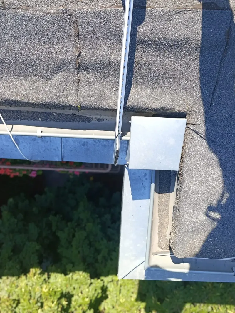
Cable run at my station: the roof edge and the flashing are places to inspect every autumn · photo: SQ5CBA
Frost, rime, wet snow
Ice on the antenna is a dielectric too
Ice has a relative permittivity of about 3, and water and wet snow add further losses. Deposited on the elements they act as an extension — resonance moves downwards.
Yagi
Bare elements
G4ZTR measured a 2 m Yagi dry and wet: after rain the whole SWR curve shifted down by about 700 kHz, in another antenna by almost 1 MHz. Ice acts similarly, and heavy rime on the directors can spoil directivity. That’s why it’s better to tune a Yagi for a good SWR slightly above the frequency you use.
Collinear
Antenna in a radome
Verticals such as the X‑200 have the radiator in a fibreglass radome. Ice settles on the radome, at some distance from the elements, so detuning should be smaller than with a Yagi — however, I haven’t found measurements for such antennas. A temporary rise in SWR during icing is normal and goes away with the thaw.
Principle
What’s a red flag
Detuning that disappears after the thaw is physics. An SWR that doesn’t return to the autumn reading after the melt most often means water in the connector or the cable, less often mechanical damage from ice. That’s exactly why you write the figures down before winter.
The weight we forget
ISO 12494 on atmospheric icing of structures warns that ice can double the normal loading on antennas and their mountings, and the weakest parts are often the small details. Hard rime has a density of 600–900 kg/m³, glaze ice about 900 kg/m³. Then there’s wind: ice increases the area the wind pushes against.
Diamond quotes a wind rating of 50 m/s for the X‑200N, and the manual recommends using guys if the mast is made up of several sections. Remember that wind maps give a 10‑minute mean at a height of 10 m over open ground — gusts, especially on a roof, are distinctly stronger.
Don’t knock the ice off
Ice on structures usually doesn’t melt away but comes off in chunks when it thaws — and damages whatever is below. Don’t go onto an icy roof to knock it off: the whole antenna on the mast is more important than a week of worse SWR. If icicles and overhangs endanger passers‑by, that’s for the building manager and a qualified crew to deal with. Your job is to report the hazard, not to go up there with a broom.
Rotator in freezing weather
The Yaesu G‑450A rotator operates down to −20 °C. In the G‑1000DXC manual Yaesu says the rotator is factory‑lubricated for maintenance‑free operation in any climate and must not be opened — user lubrication is not provided for. With heavy ice and deep frost leave the antenna parked: Hy‑Gain warns that in freezing weather the rotator turns more slowly, and an iced‑up antenna presents more wind resistance.
Yagi by a chimney after a snowstorm · photo by Jim Champion, CC BY‑SA 2.0, Flickr
Mechanics
Mast, clamps and guys
In autumn wind and rain test your fixings faster than anyone else. Better do it before they do.
Corrosion where metals meet
Aluminium and zinc paired with stainless steel will corrode — all that’s needed is moisture, and there’s always plenty of it under washers and clamps. A rule of thumb from stainless‑steel guides: a small stainless bolt in a large aluminium tube is fine; the reverse arrangement is not. A white, powdery bloom on the aluminium by a clamp is a sign the process is under way.
Stainless threads like to gall, and after a year on a roof they also seize. Hy‑Gain and Yaesu recommend greasing bolts and U‑bolts — next year you’ll undo them without an angle grinder.
Guys
Guy tension depends on temperature: in winter the wires are tighter than on a warm day. Don’t crank them up “to the max” on a sunny October afternoon. Check the wire‑rope clips — U‑bolt on the dead end, saddle on the loaded end — and the securing of the turnbuckles.
Chimney clamps
Check that the clamps haven’t loosened and aren’t biting into the chimney render, that there’s no rust on the galvanising, and that the mast is vertical. After every gale it’s worth looking at them again — the TIA standard for masts recommends an inspection after severe wind and icing.
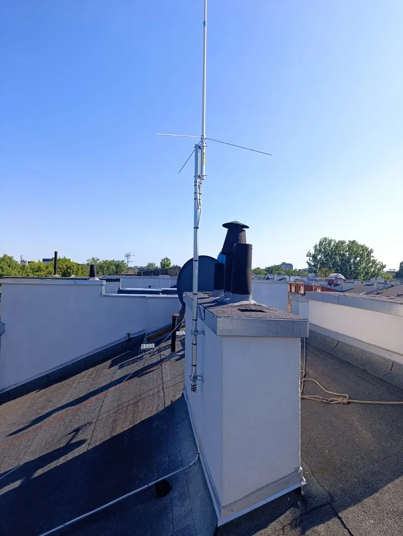
My Diamond X‑200N on a mast by the chimney · photo: SQ5CBA
In case of a storm
Earthing and lightning arrester
Thunderstorms in Poland are rare in winter — about 97% fall in April–September — but they do happen. On 17 January 2022 the PERUN system recorded over 4,600 cloud‑to‑ground strikes. Autumn is a good time to inspect the connections.
RegulationsBUILDINGThe technical conditions for buildings (Warunki techniczne dla budynków, § 192f) say that parts of an installation taken above the roof must be placed in the zone protected by the lightning‑protection system, and where the building has none — directly earthed; antenna installations that extend above the roof are to be protected by arresters. Whether this applies to a private radio amateur’s antenna isn’t clear — as a technical point of reference it’s reasonable.
ConductorsCROSS‑SECTIONAccording to materials from DEHN and Prof. Andrzej Sowa (based on PN‑EN 60728‑11, the standard for TV installations, applied by analogy to an amateur radio station): run the mast earthing conductor by the shortest route, min. 16 mm² Cu, and bond the cable screen to earth with an equipotential bonding conductor, min. 4 mm² Cu. Earthing is required except for antennas inside the building, or those at least 2 m below the roof edge or eaves and within 1.5 m of the wall — a mast above the roof doesn’t qualify.
GutterMYTHA gutter can act as an earthing conductor only with proven galvanic continuity of all joints. A cable run along a gutter doesn’t mean the gutter is earthing anything.
InstallationTENEMENTIf the building has a lightning‑protection system, the mast should be within the zone protected by the air‑termination, e.g. shielded by a separate, insulated air‑termination. Only if that’s impossible is it bonded to the system — then part of the lightning current goes into the building, so a lightning arrester and equipotential bonding are necessary. The design and any change to the air‑termination must be done or agreed by a qualified electrician. This is also the building manager’s or housing association’s matter, as is the permission for the antenna itself.
Lightning arresterCABLEA quarter‑wave arrester (with a shorted stub) is narrowband — 10–20% of the centre frequency — and the manufacturer specifies it for a particular band. If the datasheet doesn’t list both 2 m and 70 cm, choose a gas discharge arrester rated to at least 450 MHz, with a gas tube matched to the transmitter power, on an earthed plate at the cable entry. An arrester alone does not protect against a direct strike.
ThunderstormPRACTICEIcom says to disconnect the power and the antenna before a thunderstorm, and Yaesu reminds you not to touch the antenna during a storm. DARC adds an important detail: a plug pulled out and left loose next to the radio is still an induction loop — the antenna coax is best earthed, not just unplugged, when a storm is brewing. Once it’s thundering, don’t switch anything.
What it looks like in practice
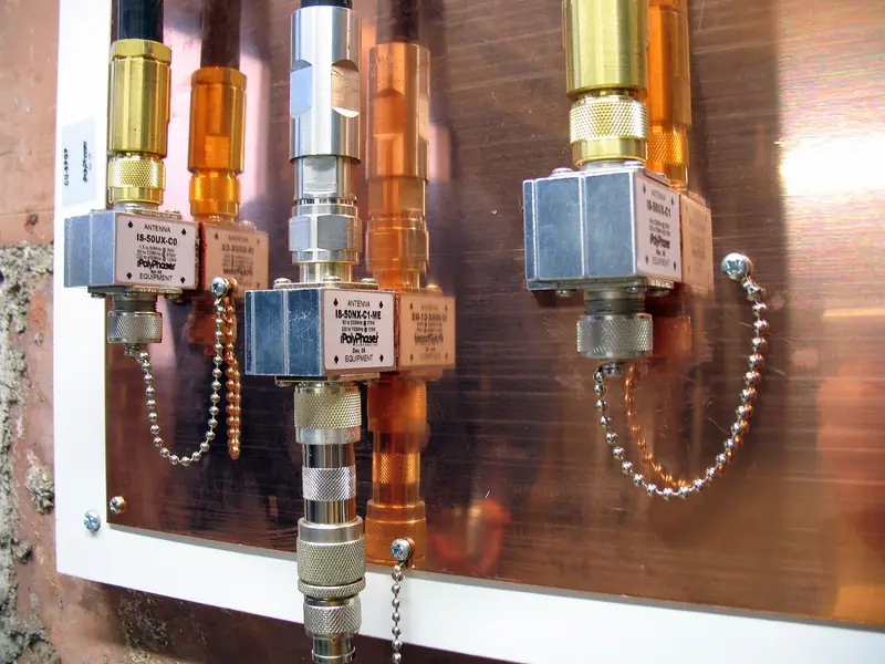
Every cable entering the building goes through its own lightning arrester, and all the arresters sit on a single common plate connected to earth. That’s what the ARRL recommends.
An autumn check is simple: terminals on the plate and on the mast with no verdigris, bolts tightened, the earth strap without breaks and sharp bends. If the arrester has a replaceable gas discharge tube and the manufacturer specifies replacement — check whether it’s due.
Arresters on a common copper plate · photo: Dan from Springfield, IL, CC BY 2.0, Commons
⚡
The Diamond X‑200 is DC‑grounded — it bleeds off static charges, but it does not replace mast earthing. The manufacturer’s manual is brief: do not fit the antenna to a mast that is not properly earthed.
To tick off
Autumn inspection checklist
Your ticks are saved in this browser, on this device — if you want to tick things off on site, open the list straight away on your phone. The button at the bottom clears everything for next year.
Electronics Notes: why SWR lies; repeater-builder.com: water in the coax; Evans (1965): permittivity of ice; LAPP: UV resistance of cables
E. Bielec-Bąkowska: thunderstorms in Poland 1949–2006 (Prace Geograficzne UJ 2013); IMGW-PIB: thunderstorms in winter and summary of the 2022 season; health and safety regulations of 1997 (§ 105) and 2003 (§ 7, § 123)
Next step
Do the maths, before you buy a cable
If the inspection ended with a decision to fit a new cable, compare the losses of several types for your length and band — on 20 m and 70 cm the difference between a thin RG‑58‑type cable and a good 10 mm cable is more than half the power.