Home  /  Guide  /  Interference (QRM)

Guide · interference

Noise from the mains:
how to find the source

One day there’s S7 of noise sitting on the band that wasn’t there yesterday. It’s almost never propagation or a faulty receiver — it’s a power supply, an inverter, an LED strip or a neighbour’s device. I show how to measure the level, recognise the source by its sound, track it down at home with a single switch, and if it’s outside — what to do and what a report to UKE (the Polish Office of Electronic Communications) looks like.

S9 = −73 dBm 1 S = 6 dB main breaker test ferrite mix 31
Photovoltaic inverter mounted on a building wall, white enclosure with control panel PV inverter — one of the most common household sources of QRM · photo: Asurnipal, CC BY-SA 4.0, Commons
Before you start guessing

Numbers first, then guesses

“It’s terribly noisy” isn’t a description you can work with. You need three things: the level, the time of day, and whether the noise is coming in via the antenna.

S

S‑meter reading

Note the noise on a few bands: 3.6 MHz, 7 MHz, 14 MHz, 145 MHz. The S number alone is enough — as long as you use the same gain and preamp every time.

hh:mm

Time of day

Noise only from dawn to dusk points to photovoltaics. Only in the evening — to lighting. All the time — to something that never switches off: a router, power supply, charger.

ANT

Antenna or chassis

Disconnect the antenna. If the noise remains, it’s coming in via the power lead or straight into the chassis — a ferrite on the antenna won’t help.

∠

Direction

Rotate a directional antenna all the way round and note the bearing of the maximum. On 2 m that’s often enough to point to a house or a pole.

What does “S9” actually mean

IARU Region 1 standardised the S scale in Technical Recommendation R.1: one S‑unit is 6 dB, and S9 corresponds to a signal at the receiver input of −73 dBm on the shortwave bands (50 µV into 50 Ω) and −93 dBm on VHF (5 µV). That’s why the same signal reads three S‑units higher on 2 m than on 20 m — it’s not a radio fault, just two different scales.

A practical takeaway: noise that rose from S3 to S7 has increased by 24 dB, i.e. almost 250 times in power. The station you could hear before has just vanished — and no antenna will make up for that.

The table alongside is there to convert a reading into a number you can put in a report or compare with a measurement a week later.

!

Most S‑meters in ham radios are not calibrated — sometimes one bar is 3 dB rather than 6. For “before and after” comparisons it doesn’t matter; for a report it’s better to give dBm from an SDR receiver.

ReadingHF (dBm)VHF (dBm)
S1−121−141
S3−109−129
S5−97−117
S7−85−105
S9−73−93
S9+10−63−83
S9+20−53−73
S9+40−33−53

From IARU Region 1, Technical Recommendation R.1 (1981). 6 dB per S‑unit.

Five minutes, zero cost

Main breaker test

One question splits two completely different scenarios: is the source in your house, or outside it? The main breaker gives the answer.

1

Battery‑powered radio, headphones

An HT, an SDR receiver with a laptop on battery, or an ordinary medium‑wave radio tuned between stations around 1 MHz. Anything that runs without the mains — otherwise you’ll cut your own power halfway through the test.

AM ~1000 kHz · or SSB 3.6 MHz · slow AGC, NB off
2

Write down the “before” level

An S‑meter reading and a short clip on your phone. Without that, after half an hour you won’t be sure whether anything changed or you just want it to have changed.

3

Turn off the main breaker

The whole house is without power, the radio keeps running on its battery. The noise stayed — the source is outside your installation: a neighbour, a pole, a line, an electric fence. The noise vanished — it’s on your side and from here on it’s just patience.

Warn the household · shut down computers and NAS properly beforehand
4

Circuit by circuit

Turn off all breakers, turn the main back on, then energise the circuits one by one and listen. The noise returns with a particular one — you’ve got the room. It’s the same method ARRL has described for years, because it works and needs nothing but your ears.

5

Plug by plug

On the identified circuit, pull out power supplies one by one. Chargers, extension leads, the router PSU, an LED‑strip controller, a desk lamp, a printer in standby. Usually the culprit reveals itself in a few minutes — and it’s usually the cheapest thing in the room.

⚡

If you have PV, remember that the inverter has its own switch and its own circuit, and the DC strings are live even when the AC side is disconnected. With PV, test during the day and do it separately: once with the inverter off, once with it on.

Identifying by ear

What it sounds like

Most sources have a characteristic rhythm or time of operation. Before you start pulling plugs, listen — you can often guess what to look for.

Scroll the table sideways →

SourceRhythm and toneWhereHow to confirm
Arcing on a power line A rough crackle in bursts, about 100 times per second (twice per 50 Hz cycle) HF, weaker on 2 m Disappears after rain, returns in dry weather. Doesn’t stop when you turn off the main breaker
Electric fence Even “tick… tick…”, roughly once per second, a broadband crackle across HF and VHF Very regular spacing. In rural areas and near pastures — the prime suspect
Switch‑mode power supply, USB charger Hissing carriers at equal spacings of a few tens to a few hundred kHz, a “comb” on the waterfall HF, often up to 2 m Disappears immediately when unplugged — even when it isn’t charging anything
PV inverter Wide, flat noise, increases with array power approx. 0.1–30 MHz Daytime only, loudest at noon, quiet with heavy cloud
Optimisers and microinverters As above plus a pronounced comb; data transmitted over the DC line HF It remains even with the inverter turned off, if the modules are in sunlight
PLC — “internet from the wall socket” Noise modulated by data traffic, it goes quiet when the network is idle 2–86 MHz (HomePlug AV2) Unplug the adapters from the sockets. Standard EN 50561‑1 requires notching the amateur bands — cheap units do this poorly
Charging an electric car Noise only while charging, disappears after unplugging 2–28 MHz (HomePlug Green PHY) The ISO 15118 standard carries signalling over the Control Pilot conductor in the charging cable
LED strips and bulbs, halogen power supplies Buzzing with a distinct 100 Hz modulation, wideband HF, sometimes 2 m Goes off with the light. A dimmer usually makes it worse
Fridge, heat pump, air conditioning with an inverter Hum that comes on cyclically, for a dozen or so minutes HF The rhythm matches the compressor’s operation — listen for when it kicks in
Router, switch, HDMI cable, monitor Single narrow ‘whistles’ at equal spacings — clock harmonics HF and VHF/UHF They’re constant, regardless of the time of day. They disappear after unplugging a single signal cable

The 100 pulses per second rhythm comes straight from the 50 Hz mains: the discharge fires at every voltage peak, and there are two per cycle. In countries with 60 Hz mains the same symptom is described as 120 pulses.

The waterfall tells you more than your ears

Three shapes, three culprits

Three interference spectrum shapes: evenly spaced carriers, a wide plateau and single spikes Comb switch‑mode power supply Plateau inverter, PLC Spikes clocks, HDMI, router

Comb means evenly spaced carriers — the spacing between them matches the switching frequency of the power supply. If the lines are, say, 130 kHz apart, you’re looking for something that runs at that frequency.

Plateau lifts the whole band at once and simply robs you of sensitivity. That’s what an inverter looks like, and that’s what PLC looks like — the difference being that PLC varies with network traffic.

Spikes stand still and never go away: they’re clock harmonics. One lands right on your favourite frequency and ruins that one alone.

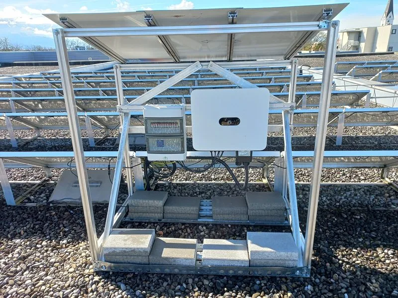
String inverter and DC surge protectors under a PV array frame, with visible runs of cable Inverter and DC wiring under the modules — the loop of those cables radiates · photo: Asurnipal, CC BY-SA 4.0, Commons
A topic in itself

Photovoltaics: DC cables are an antenna

A PV installation rarely radiates from the ‘box’. It radiates via the wiring — which is why it’s so hard to quieten after the fact.

Where it comes from

The inverter converts power by switching transistors tens of thousands of times per second. With poor filtering, harmonics of this switching reach from about 100 kHz up to 30 MHz — i.e. right across the HF bands. The inverter itself is small, but the DC string on the roof is tens of metres long and forms a loop — and that’s what radiates.

The other path is the AC wiring: the interference leaves the inverter into the house installation, spreads through the whole building and is reradiated by every cable along the way. That’s why the noise can be just as strong in a room on the far side of the house.

What really helps

  • Short, twisted DC leads — plus and minus run together, with no big loops. That’s an installation decision, costly to change after the fact.
  • Common‑mode chokes on DC and AC at the inverter — mix‑31 core, a few turns of both conductors together, as close to the unit as possible.
  • Distance between the antenna and the installation — every metre counts, and setting the antenna in a different plane to the cable run can be worth a few decibels.
  • Optimisers — if it’s specifically a module with an optimiser causing the interference, the only effective route is often to replace it with another model or dispense with them in favour of a plain string.

If the installation is new and has been interfering from day one, report it to the installer before the warranty expires: equipment placed on the market must meet electromagnetic compatibility requirements, not just ‘make electricity’.

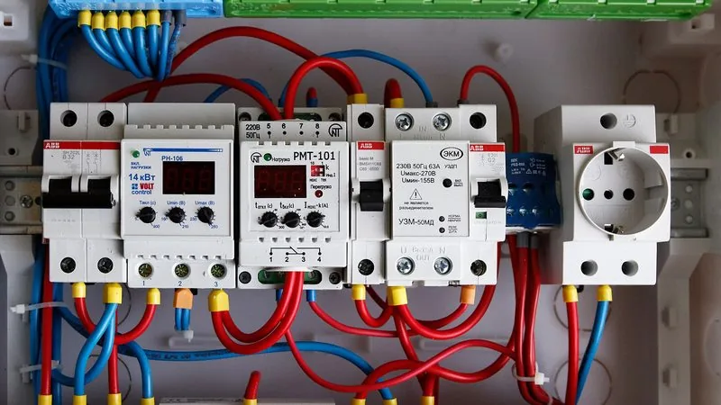
Electrical distribution board with breakers, relays and coloured wiring Consumer unit: this is where circuit bisection begins · photo: Retired electrician, CC0, Commons
When the noise remains after switching the power off

Direction finding outside the house

probe

AM radio and handheld

A common medium‑wave receiver has a built‑in ferrite antenna, i.e. a ready‑made directional antenna: the signal minimum lies along the rod’s axis. On 2 m the same role is served by a handheld with a three‑element antenna.

scale

Attenuate, don’t amplify

Close to the source the receiver will saturate and the bearing will vanish. Engage the attenuator, wind the gain back, shorten the antenna. You DF best when the signal is barely audible.

method

Three bearings

Note the direction of the maximum from three widely spaced points and intersect them on a map. One bearing is a guess, three is an address. The locator and azimuth calculator will help.

Log it, don’t memorise

When DF’ing outside the house, documentation matters, because sooner or later you’ll need to show someone what’s going on. Each time, note: date and time, frequency, level in dBm or S, the coordinates of the measurement point and the bearing. An audio recording on your phone weighs next to nothing and can settle whether it’s a fence energiser or a power line.

If the noise appears at fixed times, keep a simple log for a week. A pattern like ‘daily 6:30–8:00 and 17:00–23:00’ points straight to someone switching lights on or charging a car.

Before you accuse your neighbour

Check your own house again at the time when the noise is loudest — it happens that a device that was previously off has just started up. And make sure it isn’t propagation: on strong tropo days the 2 m band can come alive, and distant stations can be mistaken for noise. The propagation map and propagation conditions will give you a clue.

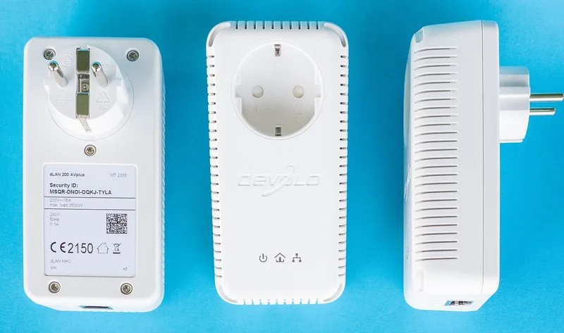
Three PLC adapters for carrying internet over the mains wiring, shown front and back PLC adaptors — operate in the 2–86 MHz band · photo: Sven Teschke, CC BY-SA 3.0 de, Commons
Cures

Ferrite, filter, distance

Ferrite isn’t magic: it works on common‑mode current flowing on the outside of the cable. For it to work, it must be the right material and in the right place.

How to fit

  • At the source, not at the radio. The core should choke the noise where it’s generated — right by the power supply, inverter, router.
  • A few turns, not just one. Impedance rises with the square of the number of turns. Five turns on an FT240 core gives many times more than a clamp fitted “straight on”.
  • All conductors together. Live, neutral and earth (or plus and minus on DC) go through the same core. A single conductor makes a differential‑mode choke and usually does nothing.
  • On the feeder too. A 1:1 common‑mode choke at the base of the antenna stops the coax acting as a receive antenna for noise from the house.
  • Cheap kit clips are most often mix 43 in a tiny size — at 3.5 MHz practically useless.

Choose the material for the band you have trouble on:

MixTypeScopeUse on
75 / 77MnZn0.15–10 MHzmedium wave and the lower HF bands
31MnZn1–300 MHzbest all‑rounder for mains leads
43NiZn25–300 MHzupper HF, 6 m and 2 m
61NiZn200–1000 MHz70 cm and up

Ranges per Palomar Engineers’ material selection table. One mix 31 core on a PSU’s mains lead does more than ten little clips scattered around the desk.

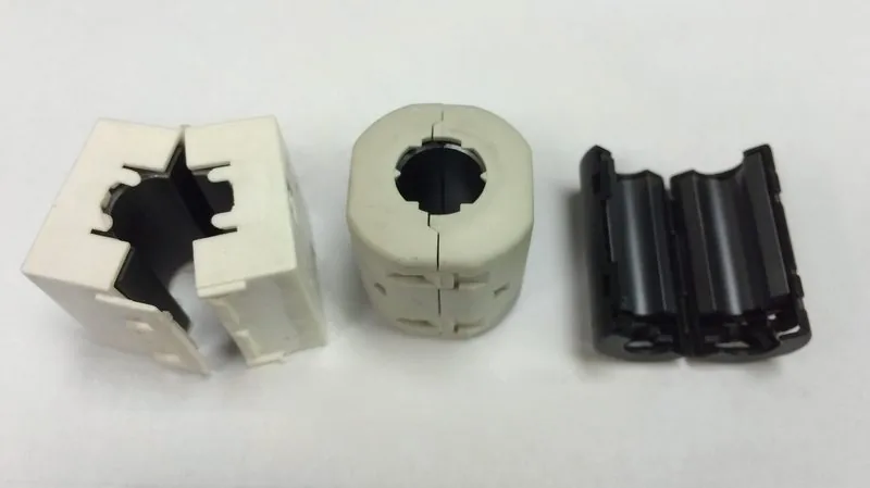
Opened clamp‑on ferrite cores in various sizes, core halves visible without housings Clamp‑on cores — the ones on the left unscrewed from their housings · photo: Unconventional2, CC BY-SA 4.0, Commons
Replacement

Sometimes it’s cheaper to buy a new one

A no‑name charger for a dozen‑odd PLN is often beyond saving with any ferrite — the input filter simply isn’t there. A branded power supply of the same rating costs a few dozen PLN and the problem disappears as a bonus.

Caution

What not to do

Don’t take other people’s gear apart or “improve” the neighbour’s wiring. Don’t add capacitors between conductors in a wall socket. A ferrite fitted externally on a finished lead is safe — anything else is an electrician’s job.

When a chat isn’t enough

Reporting it to UKE

Neighbour first, the authority later — in that order. Surprisingly often it’s enough to say something at home is “messing up the radio”, and offer a ferrite on the cable.

Who is protectedBASISUKE (the Polish Office of Electronic Communications) explicitly states that radio equipment used without a licence is not protected against interference. A radio licence for an amateur station is a real argument — CB or PMR don’t give you that.
How to report itHOWElectronically via the Electronic Services Platform pue.uke.gov.pl, via the contact form or by letter — a paper submission must be signed.
What to includeDETAILSYour radio licence number, the address and coordinates of the measurement spot, the affected frequencies, interference level, times when it occurs, and what you have already checked (main switch test, ruling out your own devices).
What happens nextPROCESSUKE staff come with measurement equipment and locate the source. Measurement and inspection work to establish the cause and location is free of charge. Once an interfering device is identified, its owner is informed it must not be used until it is repaired or replaced.
What not to reportLIMITSProblems with your own internet or mobile coverage — those go to the provider you have a contract with. TV reception trouble before you check the communal aerial and the broadcaster’s page.
i

A report only makes sense with evidence: a recording, a measurement, times and azimuth. Two weeks of notes make a far stronger case than a phone call saying it’s “terribly noisy”.

Next step

Check before you start hunting

Before you call it interference, rule out propagation conditions. The propagation map shows whether 2 m and 70 cm are carrying further than usual.