Home  /  Guide  /  J-pole antenna

Why build one

Simple, cheap and durable

A J‑pole won’t give you more range than a good collinear antenna. But it has four advantages that still make it the first antenna many radio amateurs build.

no radials

No radials

A quarter‑wave needs radials. A J‑pole has a half‑wave radiator and doesn’t require a metal ground plane underneath. The caveat: the feedline must be decoupled with a choke, otherwise the braid itself becomes the counterpoise.

short for DC

Bleeds off static charge

The two rods are joined at the bottom, so the radiator is galvanically connected to the cable’s braid. Static charge drains to earth if the mast and the cable screen are earthed at the building entry. This is not lightning protection.

50 Ω

Built‑in matching

The lower part of the antenna acts as a transformer: by moving the tap you find the 50 Ω point. You fix the centre and braid with clips, no 4:1 transformer needed. A choke on the feedline (1:1 current balun) is still required.

≈ 2.5 m

Single tube

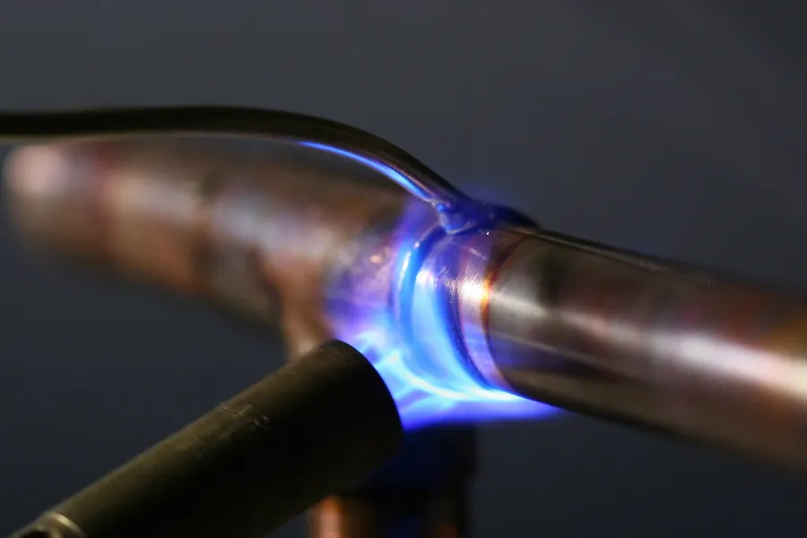
The 2 m version from Ø 15 mm tube is about 2.5 m of tubing (with spare), a tee, an elbow and two end caps from the DIY store. Plus soldering with a torch.

How it works

Half‑wave on the end of a quarter‑wave transformer

The name comes from the shape of the letter J: a long rod and a short rod alongside, joined at the bottom.

Two parts of one antenna

The upper part of the long rod (above the end of the short one) is the radiator, almost half a wavelength long. A half‑wave fed at the end has an impedance of the order of thousands of ohms (the thicker the rod, the lower it is), so a 50 Ω cable can’t be connected to it directly.

The lower section is two rods forming a quarter‑wave line shorted at the bottom. It is loaded from above by the high‑impedance radiator, and the line transforms that down: at the short the differential voltage is zero, and it rises higher up. A few centimetres above the short there is a point where the whole network, as seen from the cable, has an impedance close to 50 Ω. That’s where the tap goes.

Nominally the antenna is ¾ of a wavelength, but end effect and tube thickness make it shorter: on 2 m with Ø 15 mm tube the long rod is 1471 mm (0.71 λ), and on 70 cm 48–50 cm, depending on diameter.

i

The matching line also radiates a little, because its two rods don’t carry perfectly equal currents. That’s why the main lobe is tilted slightly upwards and the pattern isn’t a perfect circle. In an NEC‑2 model (free space) the 2 m version made from Ø 15 mm tube has a maximum of ≈ 3.1 dBi at 14°, and on the horizon 1.6–2.6 dBi, depending on azimuth (with thin wire the spread is only about 0.3 dB). A half‑wave dipole has 2.15 dBi on the horizon, so the J‑pole isn’t a “gain antenna”. Over real ground the elevation angle is determined by mounting height anyway.

Dimensions from NEC‑2

J-pole and Slim Jim calculator

Choose the band, centre frequency and material. I’ve optimised each variant separately in NEC‑2 for minimum SWR across the band (free‑space model, no mast or cable). For any other frequency within the band I scale the dimensions proportionally to wavelength. I verified in the model that such scaling, even right to the band edge, changes SWR by at most 0.01.

Band
Construction
DimensionLabel[mm]

Measure all lengths from the axis of the lower horizontal section (the short), and measure rod spacing centre‑to‑centre. The tap is the height of the clamp’s centre (with the cable) above the short’s centreline. The model result is a starting point: the mast, cable and surroundings shift the resonance, so cut the short rod long and trim to tune. For the Slim Jim slot, don’t cut the wire to the exact length: leave the slot to adjust at the very end of tuning.

Shopping list

From the DIY store

List for the 2 m version in Ø 15 mm tube. I make the 70 cm version from Ø 10 mm tube: it’s shorter and lighter, and a thick tube at such small dimensions makes tuning harder.

Materials

  • Copper tube Ø 15 mm, hard‑drawn (straight in lengths, not soft in a coil): buy 2.5 m. That’s enough for the long rod (about 1.5 m), the short one (about 0.5 m with some spare), a coupling and a 15–30 cm spigot for mounting, with margin for cutting errors.
  • 15 mm tee and 15 mm 90° elbow for soldering: from these you make the bottom of the letter J and the mast spigot.
  • Two 15 mm end caps for the top ends to keep water out.
  • Two stainless worm‑drive clamps sized to the tube diameter (for Ø 15 mm e.g. 12–22 mm) and two ring terminals or a piece of copper sheet.
  • Weatherproof box with a socket (on 70 cm an N‑type is better than SO‑239), or a short pigtail terminated directly. Keep the leads from the socket to the clamps as short as possible. Plus self‑amalgamating tape and PVC tape.
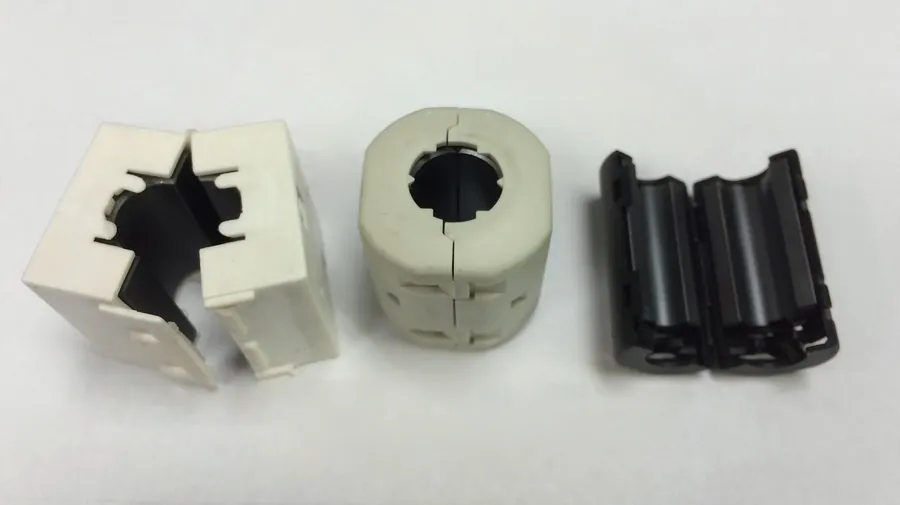
  • 50 Ω coax and material for a choke: clip‑on ferrites of a VHF/UHF mix, or a length of coax for a coil (2 m only).
  • Soft solder for copper (e.g. Sn97Cu3) with flux, or press fittings instead of soldered ones.

Tools

  • Tube cutter: cuts square and doesn’t crush the tube. A hacksaw will do a poorer job.
  • Gas torch, abrasive fleece for cleaning copper, flux brush.
  • Steel tape measure and marker: on 70 cm, millimetres matter.
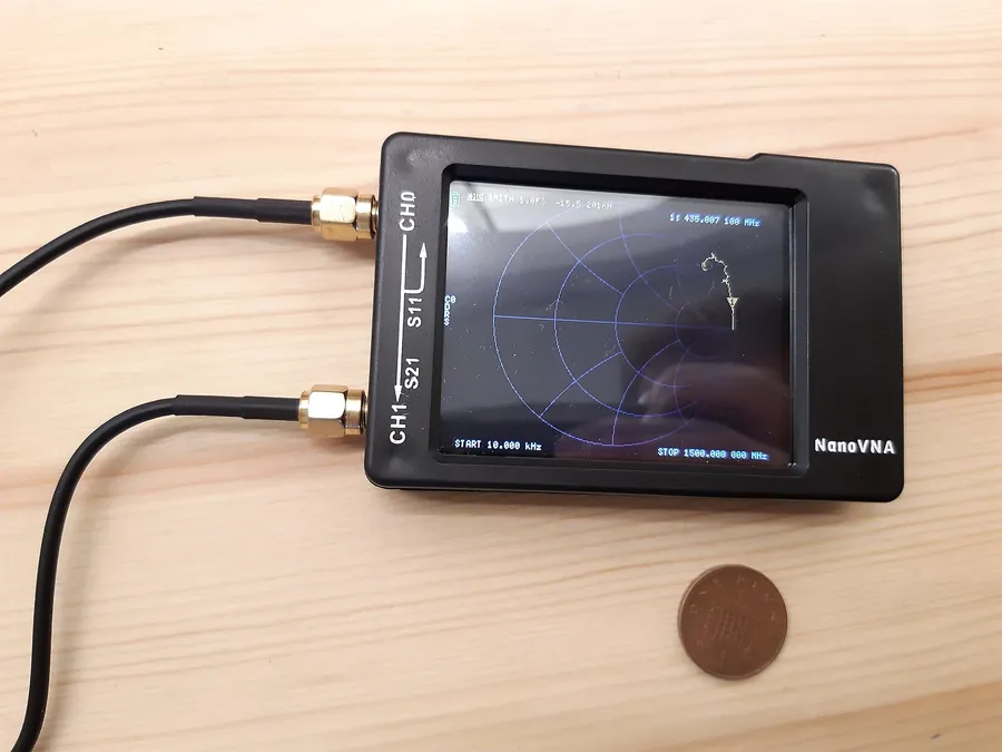
  • Analyser or NanoVNA. You can manage without (SWR meter and a radio on low power), but tuning takes longer.
  • A clamp or two U‑bolts to fix the spigot at the top of the mast (the mast ends below the short, it doesn’t run alongside the antenna).
!

Don’t fill the tube with anything and don’t paint it with metallic‑pigment paint. Clear metal lacquer is enough, or nothing: patina on copper has no noticeable effect on radiation. Clean the areas under the clamps to bare metal and seal against water, because good contact matters there.

Workshop

Build step by step

This description covers the tube‑and‑fittings version. With wire or aluminium rod you do the same; only the bottom of the letter J is bent or bolted together, and a plastic spacer keeps the rods apart.

The most common J‑pole problem

Current on the braid and the choke

The feed point lies between the two conductors of a balanced line, and coax is unbalanced. The currents in the rods aren’t equal, so some current flows onto the outside of the braid and the cable radiates like another length of antenna. That’s inherent in the arrangement, not a fault.

Symptoms

  • SWR changes when you touch the cable with your hand or re‑route it.
  • Resonance “floats” after changing the cable length, even though the antenna hasn’t changed.
  • The lobe lifts even further upwards or is uneven, because the vertical cable is radiating too.
  • You get RF on the case of the radio or the microphone at higher power.

The cure

Right below the tap (a few centimetres down, not a metre lower) make a common‑mode choke, i.e. a 1:1 current balun. A good choke has common‑mode impedance of about 0.5–1 kΩ or more at the operating frequency. You have three options:

  • Clip‑on ferrites of a material suited to the frequency: on 2 m mix 43 works well, on 70 cm materials for higher frequencies are better, e.g. 61. Use several side by side; how many depends on size. Clip‑ons of unknown material (e.g. from USB leads) — check them by measurement before you trust them.
  • Coax coil, 2 m only. Such a coil has its own resonance and is narrowband, so without measurement it’s an experiment. Don’t wind the cable tighter than its minimum bend radius.
  • Quarter‑wave sleeve (sleeve, bazooka): single‑band and bulkier, but repeatable. In a fixed installation it’s a very good solution.

It’s best to measure the choke’s common‑mode impedance with an analyser. A simple test: with a choke the SWR should change barely at all when you grab the cable below the choke.

NanoVNA in hand

Tuning: frequency first, then SWR

You have two adjustments: the short rod sets the resonant frequency, and the tap sets the match. The long rod has a weaker effect (in the model 1 cm is about 0.45 MHz on 2 m, but about 3.9 MHz on 70 cm), so cut it accurately straight away and only correct it if the first two adjustments aren’t enough.

1

Set the antenna where it will operate

Or at least 2–3 m above ground, away from metal. On the bench in the workshop the result will differ from that on the mast. Calibrate the analyser (SOL) at the end of a short test lead and measure through the choke. Don’t hold the cable or the analyser in your hand during the reading.

2

Find the SWR minimum

Sweep with an analyser over 140–150 MHz (on 70 cm 420–450 MHz). With extra length on the short rod the minimum usually falls below the band, which is as it should be. If you’re tuning with a radio and an SWR meter, transmit only within the amateur band and at minimum power.

3

Shorten the short rod

In the model, shortening the short rod by 1 cm shifts resonance up by about 1.7 MHz on 2 m. On 70 cm, shortening by 5 mm is about 7.6 MHz, so cut 1 mm at a time.

2 m: minimum at 143.3 MHz → cut about 1 cm
4

Match with the tap

Look at the resistance R at the resonant frequency (where the reactance X is near zero), not only at the SWR. R below 50 Ω: move the tap up, R above 50 Ω: down. In the model that’s about 2 Ω per millimetre on 2 m and about 5 Ω per millimetre on 70 cm. Move both clamps together; on 70 cm in 1 mm steps. The tap also shifts the frequency (on 2 m +5 mm is about +0.9 MHz, on 70 cm +3 mm is about +5 MHz), so then repeat step 3.

5

Lock and seal

Tighten the clamps, mark their position with a marker, fit the end cap on the short rod. Wrap the connector and clamps with self‑amalgamating tape, then overwrap with PVC tape as UV protection, as in the guide to preparing your antenna for winter.

Myth to debunk

“A 2 m J‑pole also works on 70 cm”

Many people believe it, because 435 MHz is exactly 3 × 145 MHz, and the radio sometimes shows a tolerable SWR. An NEC‑2 model of the same antenna says otherwise.

What the model shows

  • SWR on 70 cm: 3.5–5.7 over 430–440 MHz. A radio with protection will reduce power, and with a long cable the SWR at the radio will look better than it really is (losses in the cable mask the reflection).
  • The beam shoots upwards: a maximum of 5.3 dBi at an angle of about 52°, and −6…−1 dBi on the horizon. For a contact via a repeater 30 km away it’s the horizon that matters.
  • At 435 MHz the radiating section (971 mm) is about 1.4 wavelengths, and the whole long rod about 2.1. Currents in successive sections are in opposite phase and spread the energy into several lobes.

What to do if you want both bands

  • Two J‑poles, for 2 m and 70 cm, combined with a diplexer (VHF/UHF combiner) if you have one cable. Space them as far apart as possible, ideally one above the other, and tune each after mounting both, as they detune each other.
  • A separate 70 cm J‑pole from Ø 10 mm tube is 49 cm tall. In the model SWR < 1.5 covers 428.5–441.5 MHz.
  • A ready‑made dual‑band collinear if gain matters to you. There’s a round‑up of models in the article on base antennas.
A close relative

Slim Jim, that is a J‑pole with a folded radiator

Fred Judd, G2BCX, described the Slim Jim in 1978. The name is commonly explained by its slim build and J Integrated Matching. The radiator is folded: its end comes back down and finishes as a slot above the short rod. In the calculator L1 is the height of the folded radiator above the shorting point, and the slot is the gap between the end of the folded section and the short rod.

Is it better?

One often reads that the Slim Jim has “a lower radiation angle” and “higher gain” than a J‑pole. In my model made from Ø 2.5 mm wire on 2 m both antennas come out practically the same, and the Slim Jim’s angle even comes out 2° higher:

Wire Ø 2.5 mm · 145 MHzJ‑poleSlim Jim
Max gain2.4 dBi2.6 dBi
Angle of maximum10°12°
Horizon1.9–2.2 dBi1.9–2.3 dBi
SWR < 1.5143.6–146.5 MHz142.8–147.2 MHz

Differences of around 0.2 dB are within the accuracy of the model and are inaudible in practice. The Slim Jim has a slightly wider bandwidth, and its real advantage is practical: you can make the whole antenna, including the slot, from a single length of wire, rod or ladder line and roll it up into a rucksack.

Portable versions made from line

“Roll‑up” J and Slim Jim antennas made from 300 Ω ribbon or 450 Ω ladder line are popular. They work well for repeaters in the field, only the calculator doesn’t cover them. The line’s insulation shortens the wave (300 Ω ribbon usually nearer 0.8, windowed 450 Ω ladder line about 0.9, depending on the product), and NEC‑2 doesn’t model it. You build such antennas with some spare length and trim them on an analyser.

A bit of history

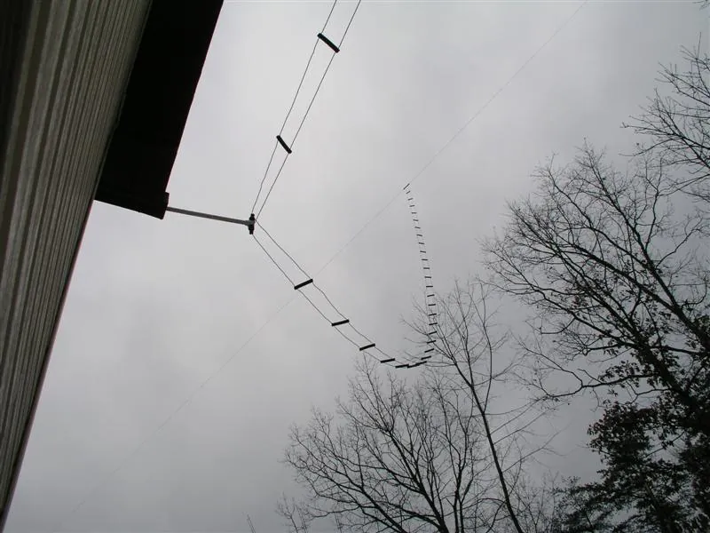
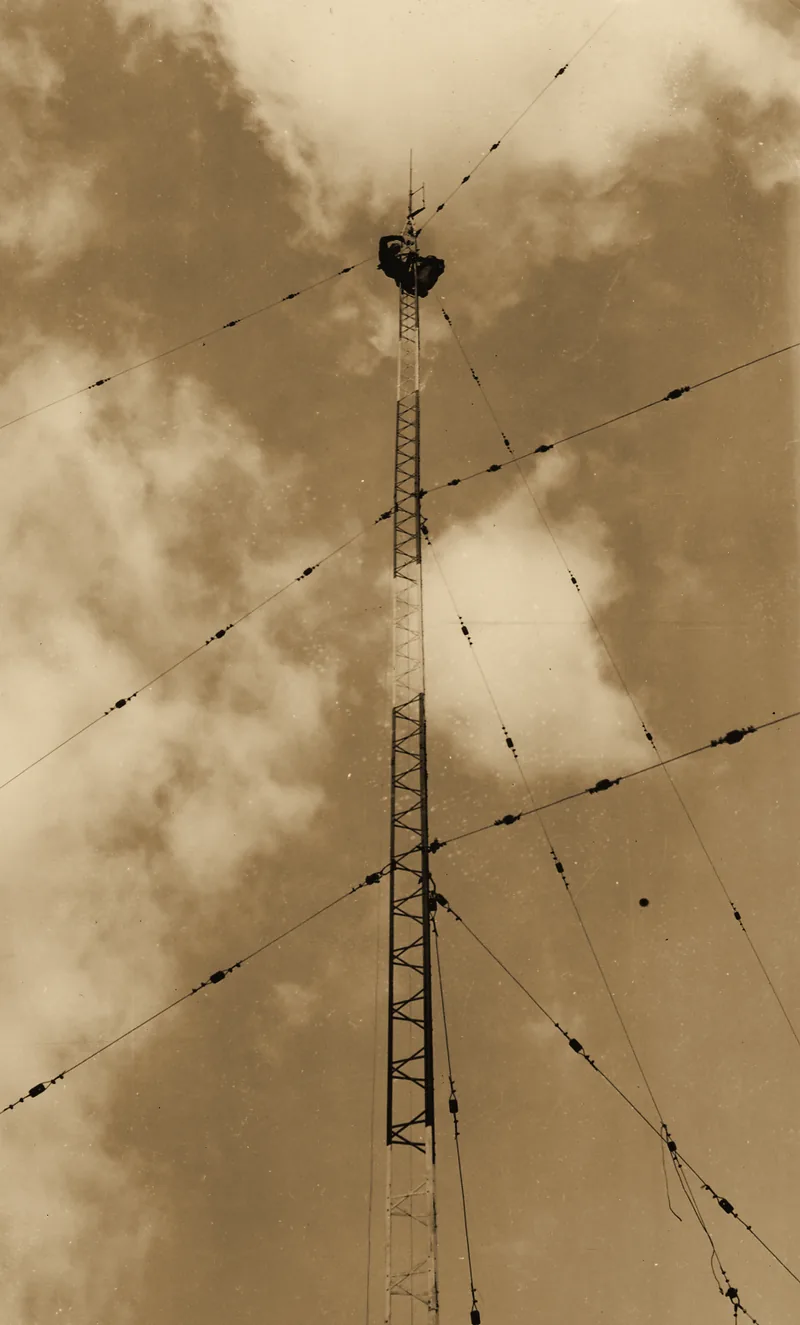
The J‑type antenna was devised by Hans Beggerow in 1909 for Zeppelin airships: a half‑wave wire trailed behind the airship was connected in series with a quarter‑wave matching line. Those airships also gave their name to end‑fed “Zepp” antennas, fed at the end by a line. In the photograph at the top of the page, US Forest Service riggers are installing and tuning a J‑type antenna at the Baldwin ranger station. According to the original description from the NARA archive it was then to be replaced by another type, “for improved radiation characteristics in the horizontal plane”. That’s the same weakness I write about above: the J‑pole doesn’t radiate perfectly evenly in all directions.

On the mast

Mounting and environment

≥ 1 λ

Away from metal

Gutters, railings, other antennas: the farther, the better. On 2 m the wavelength is about 2 m. Metal closer than that shifts resonance and pattern, which you’ll see when tuning.

at the top

Mast under the antenna, not alongside

Mount the antenna by the spigot under the short at the top of the mast, or on a horizontal standoff — the farther from the mast, the better. A mast running alongside the rods couples to the matching section and upsets the tuning. A metal mast bonded to the bottom of the antenna can also carry some RF current, so tune the antenna already mounted. On VHF, height gives you more than any change to dimensions.

earthing

Mast, earthing, storm

Earth the mast in line with building‑installation rules, and bond the cable screen to the earthing at the building entry, preferably via a surge protector. Copper shouldn’t touch aluminium or galvanised steel directly: in damp conditions galvanic corrosion develops. Disconnect the cable before a storm, never during it.

safety

High voltage at the top

During transmit the tip of the radiator carries high RF voltage, so on a balcony place the antenna out of reach of hands and head. Keep well away from power lines. On the roof of a multi‑dwelling building you need the consent of the housing association or housing cooperative, see the guide antenna and the housing association.

From experience and from the model

Eight mistakes that ruin a J‑pole

  1. Measuring from the wrong point, or cutting the tubes “to L1 length”. Dimensions are taken from the shorting axis after assembly. On 70 cm, 7 mm of the short rod is about 10 MHz — the whole band.
  2. Short rod cut “to final length”. Without spare you’ve nothing to trim, and the mast, cable and surroundings shift the resonance relative to the model.
  3. Tuning it lying down or in the workshop. Ground and metal under the antenna shift resonance by megahertz.
  4. No choke, or a random choke. The SWR “wanders”, the cable radiates, and RF may show up in the shack. The ferrite must be of a material that works on your band.
  5. Non‑parallel rods. Spacing that changes along the line changes its impedance, and then the tap is hard to set. Keep the spacing constant over the whole length of the short rod.
  6. Expecting 70 cm from a 2 m antenna. See above: SWR 3.5–5.7 and the beam into the sky.
  7. Open tube ends. Water inside freezes, and condensate collects in the elbow. Caps on top, a drain hole at the bottom.
  8. Flux residues. After a few months the joints turn green. Wash off the flux with warm water straight after soldering.
For the curious

NEC‑2 models to download

You can open them in 4nec2, xnec2c or another NEC‑2‑compatible programme. The model is in free space, without mast and cable. To see the effect of the surroundings, add ground and your own mast.

Where these numbers come from

Sources

  • Dimensions and plots: my own NEC‑2 models (NEC‑2 engine from the PyNEC library), free space, copper σ = 5.8·10⁷ S/m, extended thin‑wire kernel, equal segments ≤ λ/60 and ≤ ⅓ of the rod spacing. Model correctness checked with the Average Gain Test (AGT), deviation from −0.01 to −0.27 dB (I didn’t correct the gains, so treat them as accurate to about ±0.3 dB). Aluminium rod modelled with copper conductivity — the difference in gain is negligible. Optimisation: minimum 50 Ω SWR in‑band, for the J‑pole with the radiating section ≈ 0.47 λ.
  • The dimensions of the tube J‑pole for 2 m from the model (1471 / 500 / 46 mm at 145 MHz) are close — within about a centimetre — to the popular American builds made from ½‑inch (approx. 16 mm) copper tubing. This is only a rough comparison, not a validation of the model.
  • ARRL Antenna Book: VHF/UHF antennas, feeding and current on the braid.
  • L. B. Cebik, W4RNL: articles on modelling J‑pole and Slim Jim antennas.
  • F. C. Judd, G2BCX: the 1978 description of the Slim Jim antenna.
  • Wikipedia: J‑pole antenna (H. Beggerow 1909, Slim Jim, effect of the mast and current on the coax braid).
  • Photograph: US Forest Service, National Archives and Records Administration, NAID 2129586, public domain. Original caption: “The tower men remain aloft for 2 hours, installing & adjusting »J« type VHF antenna on top of mast at Baldwin Ranger Station. The »J« type antenna will be replaced by a type P.D.V.H.F. antenna for improved radiation characteristics in horizontal plane”.
Next step

Want more range? Build a Yagi

A J‑pole is omnidirectional and is fine for local repeaters. If you’re aiming at a specific repeater 50 km away, a directional antenna will put several times more power in that direction.